Jumper work is one of the most important skills in mobile phone hardware repair. When a smartphone comes to a repair shop with charging problems, no display, no power, or dead keys, the fault is often not the component itself—but a broken track on the PCB.
This article explains how to make jumpers in mobile phone repair to fix open tracks in a clear, practical, and technician-friendly way. It is written for beginners as well as working technicians who want to strengthen their fundamentals. The focus is on real repair logic, not shortcuts or myths.
“Track repair is not about soldering wires randomly. It is about understanding the circuit and restoring the original path.”
What Is a Track in a Mobile Phone PCB?
A track is a thin copper pathway on a printed circuit board (PCB) that carries current and signals between components. These tracks connect:
- ICs (integrated circuits)
- Resistors and capacitors
- Charging ports
- Display connectors
- Audio, network, and power sections
In modern smartphones, tracks are:
- Extremely thin
- Spread across multiple PCB layers
- Often hidden inside the board
Because of this, track damage is not always visible to the naked eye.
What Does an “Open Track” Mean?
An open track means the electrical path is broken. Current cannot flow from one point to another.
Common reasons for open tracks:
- Water or liquid damage
- Physical impact or bending
- Corrosion over time
- Excessive heat during previous repairs
- Improper soldering or component removal
When a track is open, the connected component will not receive proper voltage or signal, even if the part itself is perfectly fine.
What Is Jumper Work in Mobile Phone Repair?
Jumper work is the process of restoring a broken electrical path by creating an alternate connection using a thin wire. This wire replaces the damaged section of the PCB track.
In simple words:
- Original track = damaged
- Jumper wire = new path
If done correctly, the circuit behaves as if the track was never broken.
When Do You Need to Make a Jumper?
Jumper repair is required only after proper diagnosis.
Common situations where jumper work is needed:
- Charging section not working despite a good charging port
- Phone dead even after battery and IC checks
- Display backlight missing
- Network issues due to broken RF lines
- Speaker, mic, or vibrator not functioning
Important:
Never make a jumper without confirming an open track. Random jumpers can damage the device further.
How to Confirm That a Track Is Broken
Before making any jumper, you must prove that the track is open.
Step 1: Check the Faulty Section
First, identify what is not working:
- Charging
- Power
- Display
- Audio
- Network
Replace or test the component if required. A faulty part should be ruled out first.
Step 2: Use a Digital Multimeter (Continuity Mode)
Set your multimeter to continuity mode.
- Place one probe on the starting point of the track
- Place the other probe on the ending point
If you hear a beep, the track is fine.
If there is no beep, the track is open.
This is the most reliable basic test in mobile phone repairing.
Also read: How to Use a Multimeter in Mobile Phone Repairing
Why Tracks Are Harder to Trace in Smartphones
Older mobile phones had:
- Single or double-layer PCBs
- Visible copper lines
Modern smartphones have:
- 7 to 10 PCB layers or more
- Very compact designs
- Buried internal tracks
Because of this, technicians rely on:
- Jumper diagrams
- Schematic diagrams
- Boardview files
- Logical circuit understanding
Methods to Find Tracks for Jumper Work
There are three practical ways technicians trace tracks today. Each has its own importance.
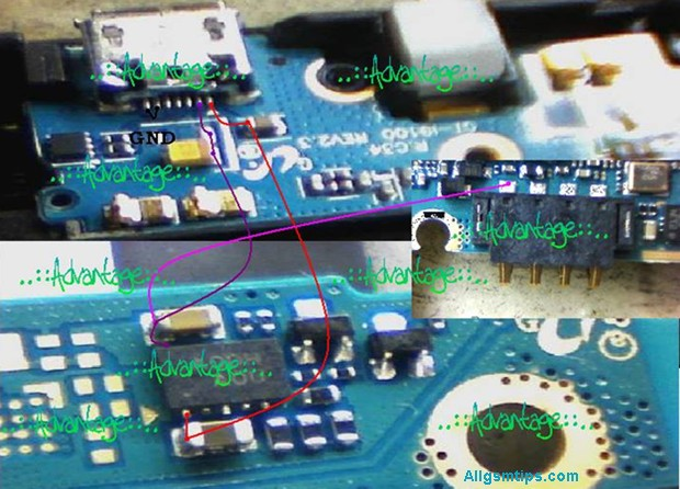
Method 1: Using Jumper Diagrams (Most Common Method)
Jumper diagrams are images that show:
- Test points
- Component connections
- Alternative jumper locations
These diagrams are widely used because they are easy to understand, even for beginners.
How to search jumper diagrams in Google correctly:
Use clear and specific search terms, such as:
- “Samsung Galaxy s24 charging jumper”
- “iPhone 17 backlight jumper solution”
- “Redmi Note 15 no power jumper diagram”
Avoid vague searches.
How to Use a Jumper Diagram Properly
- Identify the two points shown in the diagram
- Check continuity between them using a multimeter
- If continuity is missing, prepare to make a jumper
- Clean both solder points properly
- Solder a thin jumper wire between the points
If done correctly, the fault often gets resolved immediately.
Technician tip:
Always cross-check with more than one diagram if available. Some images online can be misleading.
Method 2: Using Schematic Diagrams (Professional Approach)
A schematic diagram shows the complete electrical network of a mobile phone. It includes:
- Power lines
- Signal paths
- Component values
- IC pin functions
This method requires more learning but gives maximum control over hardware repair.
How schematic-based jumper repair works:
- Identify the faulty section (example: charging)
- Locate that section in the schematic
- Understand where voltage or signal should flow
- Trace the path using a multimeter
- Make a jumper only where continuity is missing
If jumper repair does not solve the issue, the problem may be:
- Faulty IC
- Internal layer damage
- CPU or power IC failure
Method 3: Comparing With a Working PCB (Limited Use)
Some technicians compare the faulty board with a known working PCB of the same model.
How it is done:
- Check continuity on a good board
- Compare with the faulty board
- Identify missing continuity
This method:
- Requires an extra board
- Is time-consuming
- Is not always accurate
Still, in some cases, it helps when diagrams are unavailable.
Trusted Paid Schematic & PCB Diagram Services for Mobile Repair
These platforms provide official or professionally compiled schematics, layouts, bitmaps, boardviews, and track diagrams. They are widely used by experienced technicians to trace open tracks, locate components, and understand complex circuit paths.
1. Borneo Schematics – Mobile & Electronics Hardware Solutions
📌 Website: https://www.borneoschematics.com/
Borneo Schematics is a paid service that delivers daily updated schematic diagrams, hardware solutions, and bitmap files for many mobile phones and other devices. It helps technicians trace voltages, open tracks, and component connections for multiple brands.
It is often used by repair professionals who need accurate hardware diagrams and schematic guidance for troubleshooting complex faults.
2. Pragmafix Schematics – Technician Mentor & Diagram Tool
📌 Website: https://pragmafix.net/
Pragmafix provides a comprehensive schematic solution paired with training resources and repair guides for mobile phone technicians. This server-based tool includes:
- Thousands of mobile phone schematics and PCB layout files
- Circuit tracking tools for signal and power lines
- Component datasheets and block diagrams
- Repair tutorials and mentoring materials
Pragmafix aims to support technicians in both hardware and software repair learning, not only track tracing.
3. Estech Schematics (Orion by Estech) – Boardview & PCB Guides
📌 Website: https://estechschematics.com/
Estech or GSM 24 Seven provides schematic and boardview services under products like Orion Schematics. These tools are designed to assist technicians in visualizing PCB layers, track routes, and component networks across many mobile and electronic devices.
The service is useful when:
- Standard images or diagrams are not available
- Detailed boardview and circuit path views are needed for hardware troubleshooting
- Multiple brands and models must be supported
Orion and similar Estech products are popular among professionals working with both Android and Apple devices.
Why Paid Schematic Services Matter for Track & Jumper Repair
Tracked diagrams and boardviews are essential when:
- The PCB has hidden internal layers
- Simple continuity tests are insufficient
- You need exact voltage pathways
- The open track is complex or near critical ICs
Paid schematic repositories often offer:
- Multi-layer boardview files (showing hidden paths)
- Bitmap or PDF schematics with component labels
- Regular updates for new devices
- Cross-reference tools for better trace identification
Tips for Using Paid Schematic Platforms Safely
- Choose reputable sources only — avoid uncertain or pirated materials.
- Always back up data before trying advanced fixes.
- Combine diagrams with actual multimeter testing for best results.
- Learn basic schematic reading first to use these tools effectively.
Tools Required for Jumper Work
Having the right tools makes jumper repair safe and precise.
Essential tools:
- Digital multimeter
- Fine-tip soldering iron (temperature controlled)
- Thin jumper wire (copper or enamel-coated)
- Flux (good quality)
- Isopropyl alcohol for cleaning
- Tweezers
- Magnification (microscope or magnifier)
Avoid thick wires. They can short nearby components.
Step-by-Step: How to Make a Jumper Safely
Step 1: Clean the Area
Use isopropyl alcohol to remove dust, corrosion, and old flux.
Step 2: Identify Exact Jumper Points
Confirm both start and end points using:
- Jumper diagram
- Schematic
- Multimeter continuity
Step 3: Prepare the Jumper Wire
- Use very thin wire
- Strip only the required length
- Apply a small amount of flux
Step 4: Solder One End First
- Use low heat
- Ensure strong solder joint
- Avoid touching nearby components
Step 5: Route the Wire Neatly
- Keep it short
- Avoid sharp bends
- Do not cross sensitive signal lines
Step 6: Solder the Other End
- Double-check position
- Ensure no short circuit
Step 7: Test Continuity Again
Confirm beep sound across the jumper.
Common Mistakes During Jumper Work
Many beginners face failures due to avoidable errors.
Avoid these mistakes:
- Making jumper without confirming open track
- Using thick or rigid wire
- Applying too much heat
- Creating long jumper paths
- Skipping final continuity testing
“A bad jumper creates more faults than the original damage.”
When Jumper Work Will NOT Help
Jumper repair has limitations.
It will not fix:
- CPU damage
- Internal layer breaks near processor
- Severe liquid damage under ICs
- Dead memory or baseband ICs
In such cases, advanced board repair or replacement is required.
Jumper Repair vs Track Repair Using Scratching
Sometimes tracks are repaired by:
- Scratching PCB mask
- Exposing copper
- Rebuilding the track
This works only when:
- Track is on the top layer
- Damage is very small
For deeper layers, jumper wire is the safer solution.
Practical Advice From Repair Experience
- Always document your jumper paths
- Keep jumper wires short and clean
- Practice on dead boards first
- Learn reading schematics slowly
- Do not trust one image blindly
Final Thoughts
Learning how to make jumpers in mobile phone repair is a milestone for any technician. It transforms you from a parts replacer into a problem solver. With proper diagnosis, correct tools, and patience, jumper work can fix many “dead” phones that others give up on.
Focus on understanding circuits, not just soldering wires.
Good jumper work restores the original design, not just the connection.